| The
Burrow Main Menu |
| Slink's Building Collection |
History of My Interest in Robots
Back in the late 1980's a two-part article was published in Byte Magazine describing a robot that you could build yourself and program by downloads from your PC through a serial port. The first article contained the circuit card schematics and all the hardware information. The second part of the series was said to have programming examples. Parts of the project could be ordered from the author of the series, including such things as the bare circuit cards, the motors, and the wheels. Since I had no experience in making circuit cards I decided to order the circuit cards, motors, and wheels. I went to Radio shack and bought all the necessary additional components. I wrote a small program in TurboPascal to cross-compile routines for the robots processor. I waited eagerly for the second article and my ordered components. As it turns out the second article was not examples of programming the robot in its own assembler code but rather examples of programming the robot in the finished program which the author wished to sell along with finished copies of the robot. Although our order for parts had been accepted, the material was never delivered even after several toll calls from East Coast to West Coast. The project had to be abandoned, and the parts have been stored in a plastic drawer case in my computer room for the past decade. Eventually we dropped our subscription to Byte Magazine because they had stopped publishing programs we could use.
Delight in PC Magazine
In October of 1998 I was delighted to see Lego Mindstorms described in PC Magazine. According to both the magazine and Lego's Mindstorm website the product was available at TRU (Toys Backwards-R Us). Hah! The local TRU had never even heard of it. It was mid-November before I could find the product for sale here. After a week of playing with one of them, I bought two more so that I could make a community of robots and extend my work in AL to the real world.
Project Goals
My original goal was rather overly ambitious for both the system and my abilities. Nevertheless I believe it is possible. The goal was to make three robots of similar or identical physical design, run similar programs on them, measure performance, and "breed" the next generation of robots based on the relative success of the present generation. A link to a PC is required to maintain a database of success, however it is to be measured. If self-learning (neural networks) is to be a part of this project then those will also have to be maintained on the PC since that operation is much too complicated for the on-board processor. My original plan for making "feeding" though solar collectors the measure of success fell through when I was unable to find a suitable solar collector that was small enough to be carried by the size of robot that can be made with the kit. In addition my husband added his expectations that I would eventually develop a self-learning housebot from this project. Pretty ambitious goals for someone who has never built a robot and hasn't used Lego since she was 10 years old.
First Step
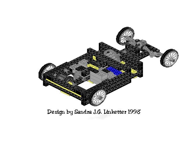
My first step is to build a sound body with steering capabilities and adequate sensory input to deal with movement around a house. I started with the projects that came with the kit but they lacked good steering control. I ordered rotational sensors so that I could control the steering, and have since brought the project back to the step of adding sensory input. In the process the robot has nearly doubled in size, which is good for the eventual goal but bad for running three at once in a cluttered household. I have attempted to make a drawing of the current state of the robot with LDraw. It cannot be drawn completely with LDraw because some of the pieces are not in the dataset for the program. To be specific, the main processing box (RCX), the motors, one gear, the proper wheels and tires, and the rotational sensor are not in the dataset. I have put wheels and tires on the drawing but the real ones are half again as big as the ones in the picture. Also omitted from this drawing is the platform which extends across the back of the chassis and supports the RCX. The steering motor, if drawn, would appear supported by the right-hand mounts, facing forward. The propulsion motor would appear supported by the left-hand mounts, facing to the rear. The rotational sensor would appear between the steering motor and the axle stub which can be seen extending into the open space.
Update 19/DEC/98 : I have modeled the motors in size and approximate shape, and the rotational sensor. Still missing is the crown gear which connects the drive motor to the differential gearbox. The wheels are still thw rong size and the RCX unit is still not pictured.